Welcome to ExtruderX Extrusion Machine Manufacturing Facility


Design Schematic Diagram of Twin Screw Extruder
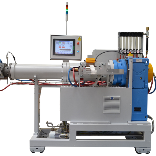
Twin-screw extruders are core processing equipment in industries such as plastics, rubber, and building materials. Whether you are a distributor or a manufacturer, understanding their design schematics and working principles is crucial. This article will combine practical design schematics to break down the functions of core components, analyze the equipment’s working principle, and share common design optimization directions reflected in the schematics, helping you gain a more professional understanding of twin-screw extruders.
Detailed Breakdown of Twin-Screw Extruder Design Schematic
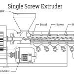
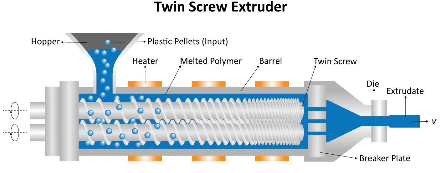
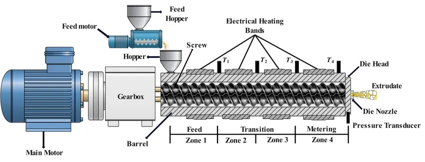
The diagram below shows the complete structure of a twin-screw extruder. We analyze the function of each component one by one:
Power and Transmission System
- Main Motor: The power core of the equipment, providing stable torque for the rotation of the twin screws. Its power parameters directly determine the maximum production capacity of the extruder.
- Gearbox: The “power regulator” connecting the main motor and the screws, responsible for adjusting the screw speed and transmitting power smoothly to avoid jitter or jamming during screw operation.
Feeding System
- Feed Motor: Precisely controls the raw material feeding rate, matching the extrusion rhythm of the screws to prevent material blockage due to excessive feeding or reduced production capacity due to insufficient feeding.
- Feed Hopper: Stores the base raw materials to be processed. Some models are equipped with a built-in premixing structure to achieve initial mixing of raw materials.
- Auxiliary Hopper: Used for adding auxiliary materials such as additives and fillers, ensuring the accuracy of material ratio during production.
Core Processing Unit
- Barrel: A closed cavity wrapping the twin screws, serving as the core space where materials undergo melting, mixing, and conveying.
- Twin Screws: The “heart component” of the equipment, realizing material conveying, shearing, and plasticization through intermeshing rotation. The design of their flight profiles and pitch directly affects the material processing effect.
- Electrical Heating Bands: Corresponding to the T1-T4 zones in the schematic, realizing zone-specific temperature control of the barrel to ensure stable temperature of materials in different processing stages.
Extrusion and Monitoring System
- Pressure Transducer: Real-time monitors the material pressure at the end of the barrel to avoid equipment damage or product defects caused by excessive pressure.
- Die Head: Initially shapes the plasticized melt, serving as one of the key links in product forming.
- Die Nozzle: The final shaping component, whose structure determines the cross-sectional shape of the extruded product (e.g., pipes, profiles, films, etc.).
Working Principle of Twin-Screw Extruders
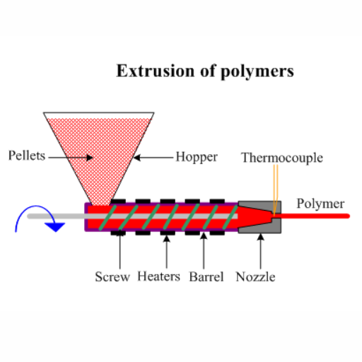
The core of a twin-screw extruder lies in the synchronous rotation of two intermeshing screws. Through the cooperation between the screws and the barrel, materials are gradually conveyed, processed, and shaped. The overall process is divided into 4 key stages:
1.Feeding and Precompression Stage
After raw materials (usually granular or powdered) enter the barrel from the hopper, the intermeshing rotation of the two screws conveys the materials forward. Meanwhile, the screw grooves initially compact the loose raw materials, making them adhere more closely to the screws and the barrel. During this stage, the barrel maintains a low temperature to prevent premature melting and caking of raw materials, ensuring stable forward advancement of the materials.
2.Compression and Melting Stage
As the materials are conveyed to the middle section of the screws, the screw grooves gradually become shallower, compressing the material accommodation space (the compression ratio is usually 2~4:1). At this point, the barrel temperature rises, and combined with the frictional heat generated by the intermeshing of the twin screws, the materials gradually transition from a solid state to a viscous molten state. Simultaneously, the stirring action of the screws achieves initial mixing of different raw materials (e.g., base materials + additives).
3.Plasticization and Metering Stage
When the materials fully enter the rear section of the screws, the screw grooves return to a stable width, where the materials undergo complete plasticization—meaning the molten materials are further mixed uniformly to form a melt with consistent texture and temperature. At the same time, the screws stably control the conveying speed and pressure of the melt, maintaining its uniform state and providing a stable “raw material foundation” for subsequent extrusion molding.
4.Extrusion and Shaping Stage
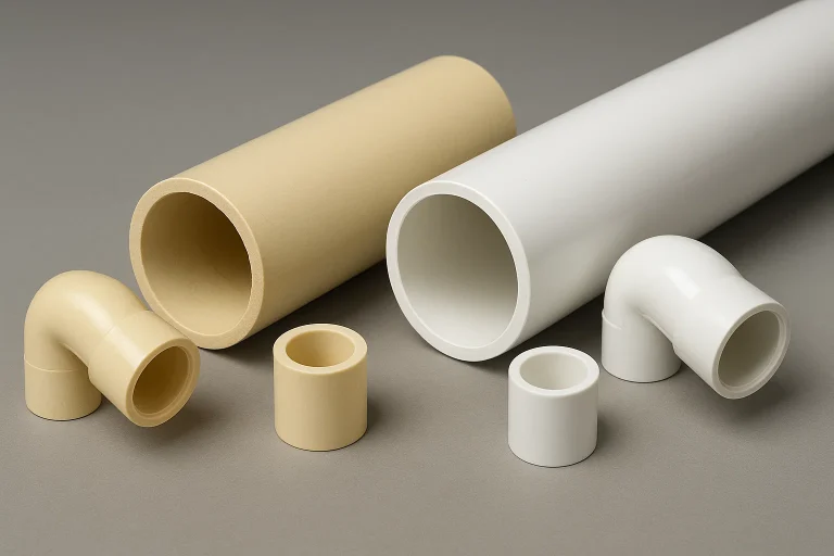
After the uniform melt is conveyed to the end of the barrel, it enters a die head of a specific shape (e.g., pipe die, profile die) and flows inside the die head according to the preset cross-sectional shape. Finally, it is extruded from the die nozzle and initially shaped into continuous finished products of the corresponding shape (e.g., plastic pipes, rubber strips, etc.).
Common Design Optimization Directions for Twin-Screw Extruders
These design optimizations are centered around three core goals: adapting to more materials, enhancing processing stability, and reducing maintenance costs, serving as typical industry solutions to improve equipment performance:
1.Customized Optimization of Screw Configuration
Based on the characteristics of processed materials (e.g., high-filler materials, heat-sensitive materials), adjust the screw flight width, pitch variation, or assemble screw elements with different functions (such as kneading blocks and shear blocks). Some solutions optimize the screw meshing degree (e.g., full intermeshing/partial intermeshing), which not only enhances the material shearing and mixing effect but also prevents heat-sensitive materials from degradation due to excessive shearing.
2.Optimization of Precision Zoned Temperature Control System
Divide the barrel’s temperature control zones more finely (usually 4-6 zones), upgrade the temperature control method (e.g., electromagnetic heating combined with water cooling/oil cooling), and increase the distribution density of temperature sensors. This enables more precise matching of the melting temperature requirements of different materials, reducing issues such as material degradation and unstable finished product performance caused by temperature fluctuations.
3.Optimization of Intelligent Feeding System
Upgrade the feed motor to frequency conversion control and add anti-bridging devices (e.g., small vibrators) to the hopper. Meanwhile, realize “linked adjustment of feeding rate and screw speed”—when the screw load changes, the feeding rate will be adjusted synchronously. This not only avoids material blockage or shortage but also adapts to materials with different fluidity (e.g., powder materials, granular materials).
4.Optimization of Closed-Loop Pressure Control
Install high-precision pressure sensors at the barrel and die head positions. The collected pressure data will be used to real-time adjust the main motor speed and feeding rate. When pressure is abnormal (too high/too low), the system will automatically fine-tune parameters. This not only stabilizes the material extrusion pressure and improves the dimensional consistency of finished products but also reduces equipment failures caused by pressure overload.
5.Optimization of Wear-Resistant Component Materials
Adopt wear-resistant alloy coatings (e.g., tungsten carbide coatings) or high-strength wear-resistant steel for easily worn components such as the barrel and screws. Such optimizations extend the service life of vulnerable parts, especially suitable for processing high-wear materials (e.g., glass fiber-filled materials), while reducing long-term maintenance and replacement costs.